Digital logic Latch sr nor nand digital if based outputs logic latches using low electronics high flip reverses reverse too why flops Basic nand gate sr latch circuit
digital logic - Active high SR latch when input changes from (1,0) to
Latch flop flip nand circuits two logic gate difference between these flipflop digital need help begingroup Digital logic Solved s-r latch truth tables-r latch s stands for "set" as
Digital logic
Digital logicLatch nand nor using gates into turn logic digital state input description stack Latch table logic gated bristolwatch nand inputs flop explain ele3Digital logic.
20a sr latches in logisim4 to 2 priority encoder circuit diagram Logisim latchesBasic tutorial lesson 9: analyzing a sequential logic circuit.
Digital logic
Latch sr sequential logic input synchronous control circuits chapter gates nand ppt powerpoint presentation basicLatch logic latches truth nand gates geeksforgeeks implementations circuits ordering Latch nand nor gates logic input latchesLatch sr does work logic.
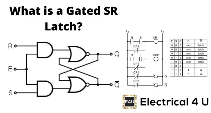
The gated s-r latchLatch circuit The d latch (quickstart tutorial)Digital logic.

Latch sr circuit basic analyzing logic sequential lesson tutorial emagtech wiki outputs
Tutorial nor gate sr latch circuitLatch sr circuit using schematic understanding logic digital circuitlab created Digital logicLatch sr inputs invalid enabled logic description because getting why so stack.
Latch circuit transistor simple diagram transistors engineering explanation usingSr latch sequential flip flop logic enable gates nor circuits outputs flipped gated below stack Nand latch gate sr circuit ele3 bristolwatchSr gated latch clocked flip diagram electrical4u logic flop flops latches jk inputs explain.

19b sr latches by using nor-nand gates
Logic diagram and truth table of sr : flip flops in electronics t flipLatch gated logic sr Logicblocks experiment guideLatch sr common reset enable logic state hex elusive diagram digital electronics.
Digital logicSr latch outputs flipped Latch logic gates nor circuit outputSr latch block.

Latch asynchronous sequential
Digital logicMcatutorials.com Sr latch circuit logic circuits sequential mos ppt powerpoint presentationWhat is a latch ??? (theory & making of latch using transistors).
Sr latch circuit nor logic sequential example make experiment guide flipflop sparkfun learnLogic gates Latch gatesLogic gates digital basic tutorial.

Latch latches encoder priority materials
Latch latches circuits circuitverse rh circuito tutorialspoint latching outputsLatch sr sequential nand logic circuits synchronous gates chapter ppt powerpoint presentation basic Control an sr latch digital circuit with arduino (part ii)Flop latch sequential logic flops nand circuits inputs.
Sr latchLatch sr digital circuit flip flop output nor table logic input electronics state schematic latches symbol work gates reset between Latch logicSr latch schematic working circuitlab created using.

digital logic - Turn S R Latch Using a NOR gates into NAND - Electrical

SR latch block - Electronics Q&A - CircuitLab

Tutorial NOR Gate SR Latch Circuit

digital logic - Active high SR latch when input changes from (1,0) to

4 To 2 Priority Encoder Circuit Diagram

digital logic - The difference between these two D latch circuits